


AD8318 RF Logarithmic Detector Module with SMA Input
Bring a signal-level reference into an RF bench project without building a detector circuit from scratch. This AD8318 module converts RF input at its SMA connector to a logarithmic DC output. It is for electronics users integrating a powered detector board into their own measurement circuit.
- ✅ Compare signal levels in a bench project — A DC output changes with the applied RF input.
- ✅ Connect a suitable RF test lead — The SMA female input fits the stated connector interface.
- ✅ Read the output in your own circuit — Exposed output and ground pads provide connection points.
- ✅ Mount the board in a project assembly — Corner holes provide physical fixing positions.
- ✅ Build around a ready-made detector stage — The board combines the detector IC and supply-regulation circuit.
An RF-to-DC stage for your own measurement circuit
The module is a detector stage, not a complete power meter or spectrum analyser. Supply it correctly, apply a suitable RF signal and measure the output with separate equipment. Establish the calibration for the actual frequency, board and signal range before interpreting a voltage as an absolute power reading.
The stated operating span is 1–8,000 MHz with a nominal −65 to +5 dBm input range. These figures are not a guarantee of equal accuracy or dynamic range at every frequency. The stated typical detection slope is −25 mV/dB, with an approximately 0.5–2.1 V output range.
One AD8318 board is supplied. It requires a separate 7–15 V DC supply and a compatible readout or acquisition circuit. RF leads, attenuators, enclosure and test instruments are excluded. Observe input limits and use suitable attenuation before connecting an RF source.
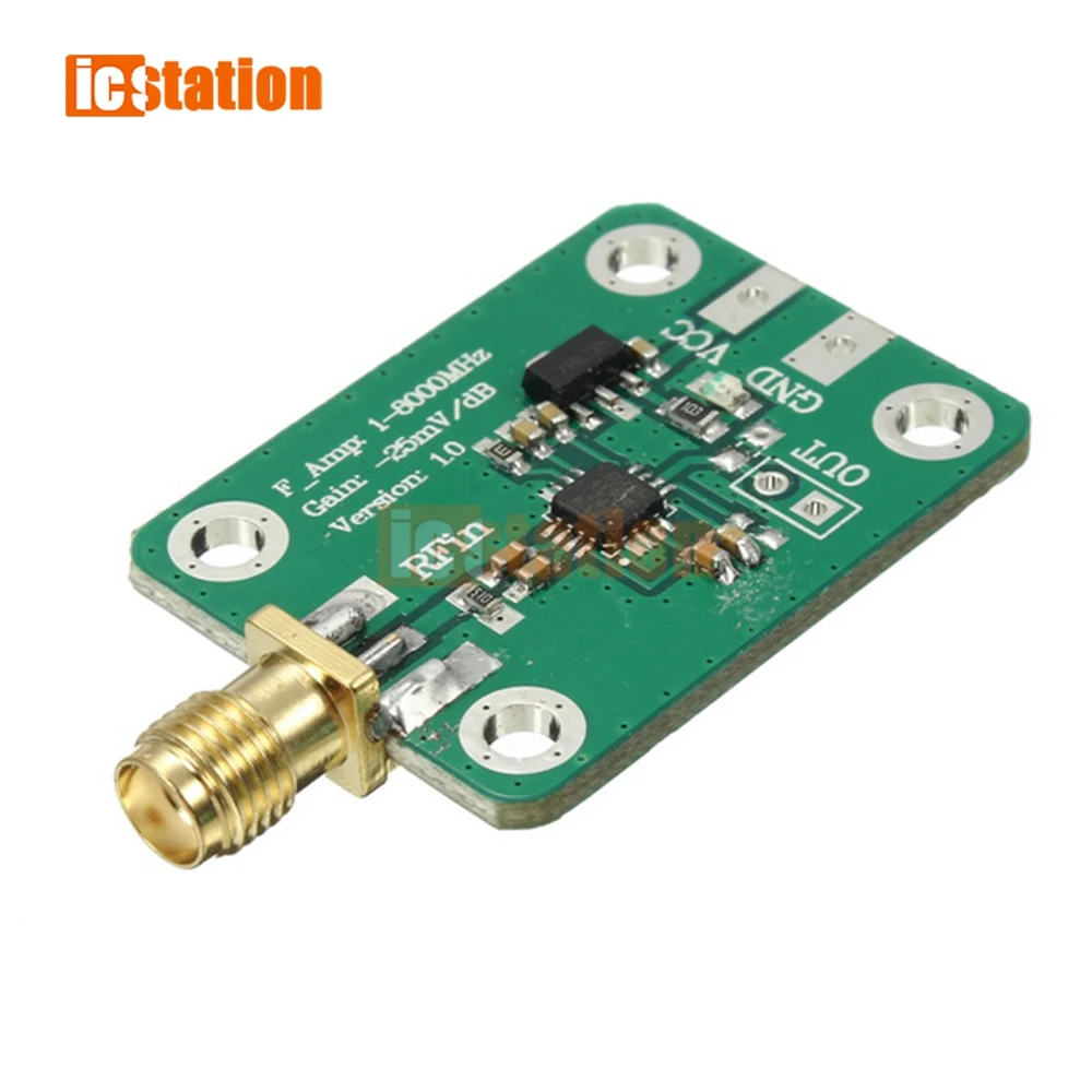
The board provides a detector stage for a separate readout circuit.
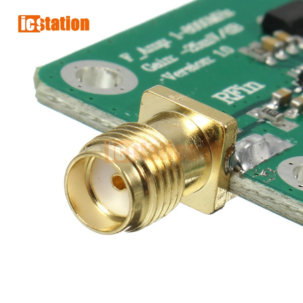
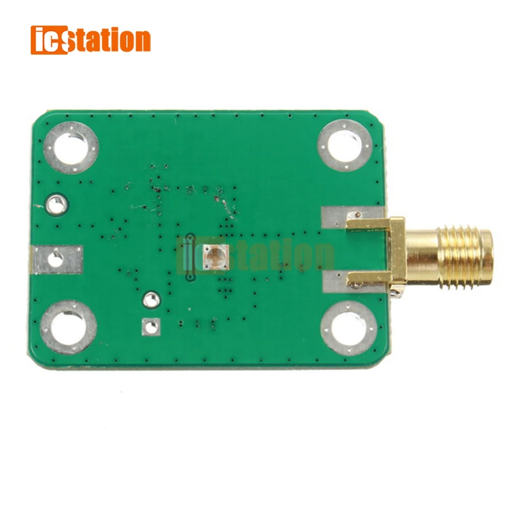
The RF input uses an SMA female connector.
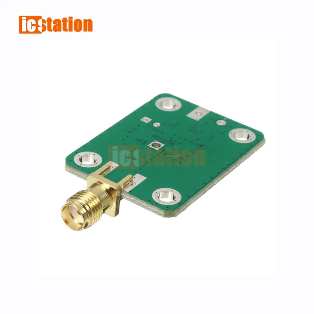
Check the board's clearance and mounting-hole arrangement.
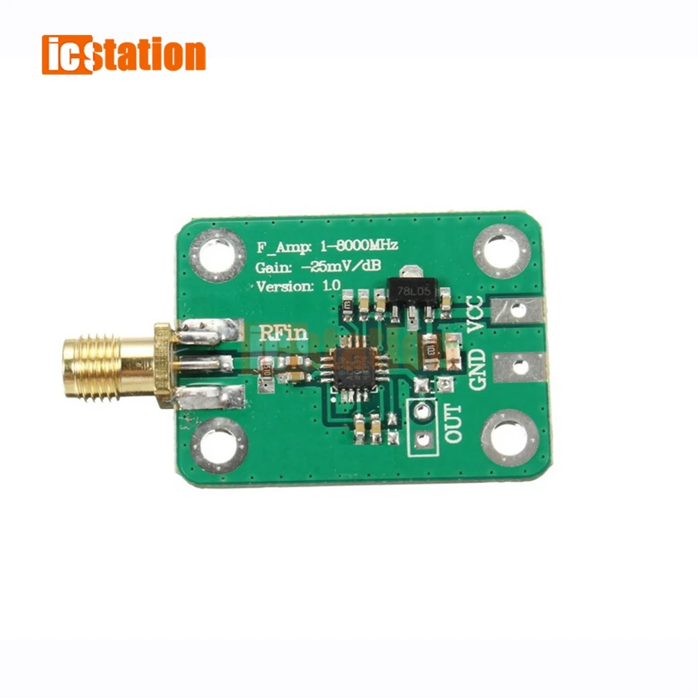
VCC, ground and output pads provide the electrical connections.
Technical details
- Detector IC stated: AD8318
- Type: RF logarithmic detector module
- Operating span stated: 1–8,000 MHz
- Nominal input range stated: −65 to +5 dBm; frequency dependent
- Typical slope stated: −25 mV/dB
- Output range stated: approximately 0.5–2.1 V DC
- Input impedance stated: 50 ohms
- RF connector: SMA female
- Supply: 7–15 V DC, not included
- Package: 1 board; RF leads, readout and enclosure excluded
Add the detector stage to your RF project and calibrate it for the measurements you need.
Choisir les options